AWS Architecture Diagram
Purpose: This document provides a multi-level visual reference of HungryHub’s AWS infrastructure, intended for engineers, DevOps, and architects who need to understand the system topology, network boundaries, and deployment pipelines.
Audience: All-team reference — backend engineers, DevOps, and technical leads.
Last updated: 2026-03-06
Overview of Diagram Levels
The architecture is broken down into four progressive levels of detail:
| Level | Focus |
|---|---|
| Level 0 | Full system overview — all major AWS services and their relationships |
| Level 1 | VPC and network segmentation — how traffic is isolated and routed |
| Level 2 | CI/CD and service internals — deployment pipelines and compute details |
| Level 3 | Deep-dive into specific service components and integrations |
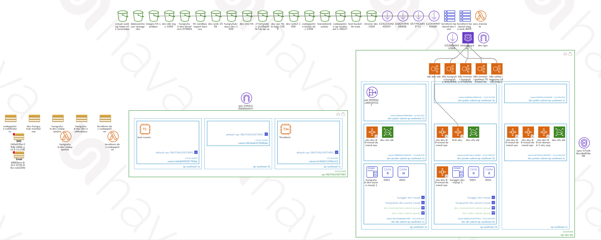
Level 0 — System Overview
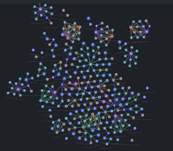
This diagram shows the complete high-level picture of all AWS services in use, their groupings, and how they connect. Traffic originates from users via Cloudflare, passes through the load balancer into the production EKS cluster, and relies on a shared data layer. The CI/CD pipeline feeds built images from GitHub into the cluster automatically.
graph TB
    Users([Users\nMobile App / Web]) --> CF[Cloudflare CDN]
    CF --> ALB[AWS ALB\nLoad Balancer]
    ALB --> EKS

    subgraph EKS["AWS EKS — Production (ap-southeast-1)"]
        HHServer[hh-server Pods]
        Sidekiq[Sidekiq Workers]
        RecService[rec-service]
    end

    EKS --> RDS[(AWS RDS\nPostgreSQL)]
    EKS --> Redis[(ElastiCache\nRedis)]
    EKS --> Memcache[(ElastiCache\nMemcached)]
    EKS --> S3[(AWS S3)]

    subgraph CICD["CI/CD Pipeline"]
        GitHub[(GitHub)] -->|push to master| CP[AWS CodePipeline]
        CP --> CB[AWS CodeBuild]
        CB --> ECR[(AWS ECR\nDocker Registry)]
    end

    ECR --> EKS
    SSM[AWS SSM\nParameter Store] --> EKS

    subgraph Staging["Staging — DigitalOcean"]
        DOK8s[DigitalOcean K8s Clusters\nhh-engineering / hh-ballbot / hh-venus]
    end
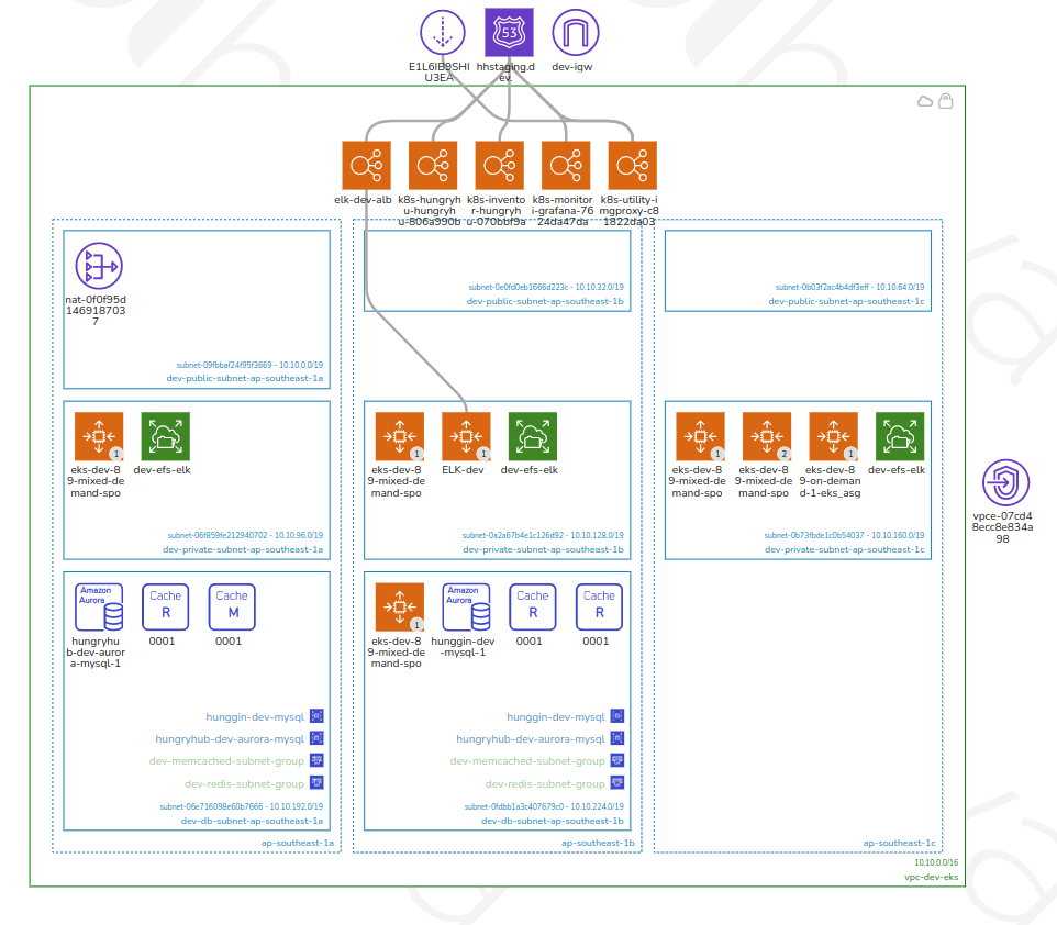
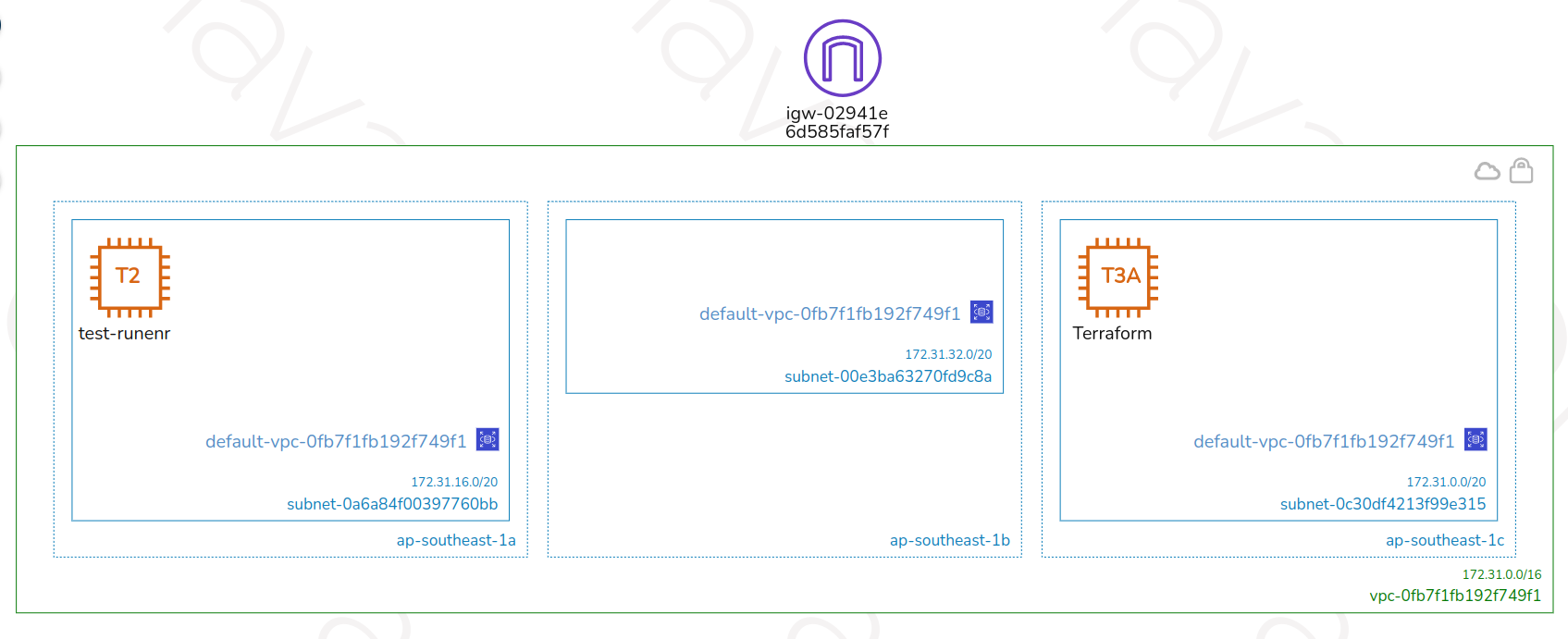
Level 1 — VPC and Network Segmentation
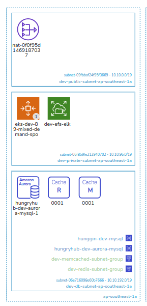
This level breaks down the Virtual Private Cloud (VPC) layout, showing how the infrastructure is partitioned into subnets, availability zones, and security boundaries. The production VPC isolates compute and data tiers in private subnets, with public subnets hosting only the load balancer and NAT gateway. The sandbox VPC mirrors this structure for pre-production workloads.
VPC 1 — Production (ap-southeast-1)
graph TB
    Internet([Internet]) --> IGW[Internet Gateway]

    subgraph VPC1["AWS VPC — Production"]
        subgraph PubA["Public Subnet — AZ-A"]
            ALB_A[ALB Node]
            NAT_A[NAT Gateway]
        end
        subgraph PubB["Public Subnet — AZ-B"]
            ALB_B[ALB Node]
            NAT_B[NAT Gateway]
        end
        subgraph PrivA["Private Subnet — AZ-A"]
            EKS_A[EKS Worker Nodes\nOn-demand + Spot]
            RDS_Primary[(RDS Primary\nr5.xlarge)]
        end
        subgraph PrivB["Private Subnet — AZ-B"]
            EKS_B[EKS Worker Nodes\nOn-demand + Spot]
            RDS_Reader[(RDS Reader Replicas\nx2–3)]
        end
        subgraph DataSubnet["Data Subnet"]
            Redis_LRU[(ElastiCache Redis\nLRU — m6g.xlarge)]
            Redis_Sidekiq[(ElastiCache Redis\nSidekiq)]
            Memcache[(ElastiCache\nMemcached)]
        end
    end

    IGW --> PubA
    IGW --> PubB
    ALB_A --> EKS_A
    ALB_B --> EKS_B
    NAT_A --> EKS_A
    NAT_B --> EKS_B
    RDS_Primary --> RDS_Reader
    EKS_A --> Redis_LRU
    EKS_B --> Redis_LRU
    EKS_A --> Memcache
    EKS_B --> Memcache
VPC 2 — Sandbox / Pre-production (ap-southeast-1)
graph TB
    subgraph VPC2["AWS VPC — Sandbox"]
        subgraph SandboxPublic["Public Subnet"]
            SandboxALB[ALB Node]
            SandboxNAT[NAT Gateway]
        end
        subgraph SandboxPrivate["Private Subnet"]
            SandboxEKS[EKS Worker Nodes\nSandbox Cluster]
            SandboxRDS[(RDS Sandbox DB)]
        end
    end

    GitHub[(GitHub\npreprod branch)] -->|auto deploy| SandboxCP[AWS CodePipeline\nSandbox]
    SandboxCP --> SandboxEKS
    SandboxNAT --> SandboxEKS
    SandboxALB --> SandboxEKS
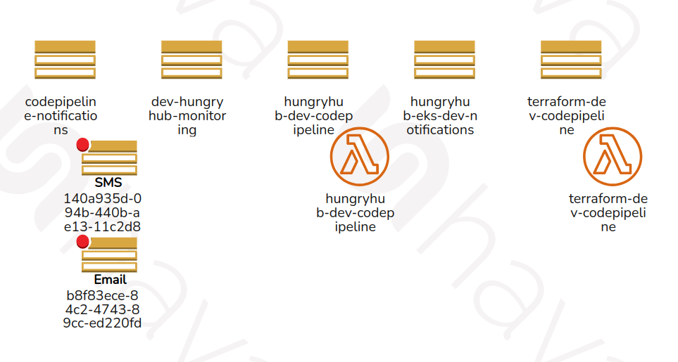
Level 2 — CI/CD Pipeline and Service Internals
This level details the deployment pipeline and individual service configurations. It covers CodePipeline stages, build processes, and service-level interactions. On merge to master, CodePipeline triggers automatically; on preprod, the sandbox pipeline triggers. Terraform infrastructure changes are managed through a separate CodePipeline (production requires manual release approval; sandbox auto-deploys on dev branch push).
CI/CD — Application Deployment
flowchart LR
    GitHub[GitHub] -->|merge to master| CP

    subgraph CP["AWS CodePipeline — App"]
        Source[Source\nGitHub] --> Build[Build\nCodeBuild] --> Deploy[Deploy\nEKS Rolling Update]
    end

    Build --> CB[AWS CodeBuild\nDocker build & push]
    CB --> ECR[(AWS ECR)]
    Deploy --> EKS

    subgraph EKS["AWS EKS — hungryhub namespace"]
        HHServer["hh-server Pods\n(min 10 / max 1000)"]
        SidekiqDefault["sidekiq-default"]
        SidekiqCritical["sidekiq-critical"]
        SidekiqLow["sidekiq-low"]
    end

    ECR --> EKS
CI/CD — Infrastructure (Terraform)
flowchart LR
    GitHub2[GitHub\nterraform repo] --> TF_CP

    subgraph TF_CP["AWS CodePipeline — Terraform"]
        TF_Source[Source] --> TF_Plan[Plan] --> TF_Approve{Approve?\nproduction: manual\nsandbox: auto} --> TF_Apply[Apply]
    end

    TF_Apply --> Infra[AWS Infrastructure\nEKS / RDS / ElastiCache / VPC]
Level 3 — Component Deep Dive
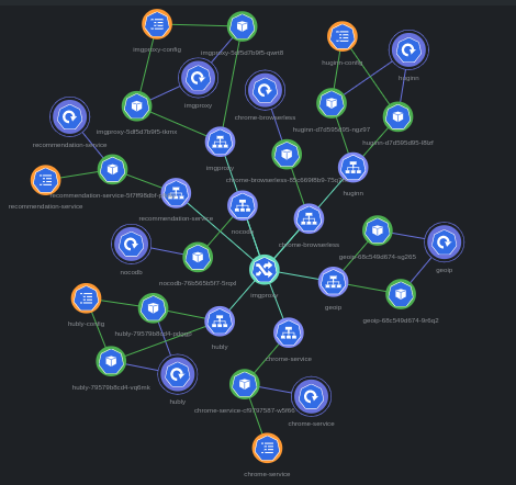
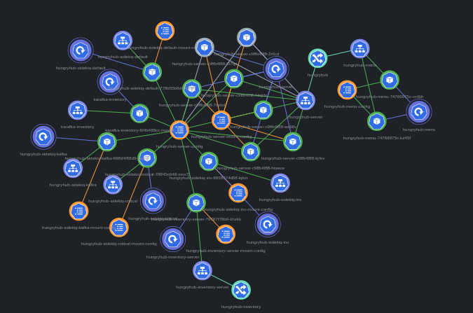
Level 3 provides the most granular view of specific components, covering internal configurations, integrations with external services, and data flow at the system boundary level.
EKS Cluster Internals — Production
graph TB
    ALB[AWS ALB] --> HHServer

    subgraph EKS["AWS EKS — Namespace: hungryhub"]
        HHServer["hh-server (Rails API)\nmin: 10 pods, max: 1000 pods"]
        RecService["rec-service\nrec.hungryhub.com"]

        subgraph SidekiqWorkers["Sidekiq Workers"]
            SidekiqDefault[sidekiq-default]
            SidekiqCritical[sidekiq-critical]
            SidekiqLow[sidekiq-low]
        end
    end

    subgraph DataLayer["Data Layer"]
        RDS[(RDS PostgreSQL\nhh-production-db\nr5.xlarge primary)]
        RDS_R[(RDS Readers\n2–3 replicas)]
        RedisLRU[(ElastiCache Redis\nLRU Cache\nm6g.xlarge / m6g.8xlarge on event)]
        RedisSidekiq[(ElastiCache Redis\nSidekiq Queue\nm6g.large / m6g.xlarge on event)]
        Memcache[(ElastiCache Memcached\n2 nodes / 20 on event)]
    end

    SSM[(AWS SSM\nParameter Store)] -->|env vars at deploy| EKS
    HHServer --> RDS
    HHServer --> RDS_R
    HHServer --> RedisLRU
    HHServer --> Memcache
    SidekiqDefault --> RedisSidekiq
    SidekiqCritical --> RedisSidekiq
    SidekiqLow --> RedisSidekiq
    RDS --> RDS_R
Scaling Strategy — Event vs Normal Days
graph LR
    subgraph Normal["Normal Days"]
        N1[hh-server: min 10 / max 1000]
        N2[RDS Primary: r5.xlarge]
        N3[RDS Readers: 2 replicas]
        N4[Redis LRU: m6g.xlarge]
        N5[Memcached: 2 nodes]
    end

    subgraph Event["Event Days (Big Event: 150k req/min)"]
        E1[hh-server: min 750 / max 1500]
        E2[RDS Primary: r5.xlarge]
        E3[RDS Readers: 3 replicas, 25% autoscale]
        E4[Redis LRU: m6g.8xlarge]
        E5[Memcached: 20 nodes]
    end

    Jenkins[Jenkins\njenkins.hungryhub.com] -->|scale-infra pipeline| Normal
    Jenkins -->|scale-infra pipeline| Event